Introduction:
If high resolution aerial imagery is not available or too
expensive for your study area, you may have to use an unconventional method to get
them yourself. In this week’s project,
we explored the use of balloon mapping to gather detailed images of the earth’s
surface. Using a simple digital camera,
we will be capturing many images to be mosaicked into a large, detailed
photograph of our campus. The following
report shows the preliminary processes to ensure a successful launch of both a
low altitude and a high altitude balloon launch. This project is far from completion and I
expect numerous revisions to our methods as we begin field testing our rigs.
Methodology:
It was important to ensure both our high altitude rigs and
our low altitude rigs were capable of flight depending upon their
payloads. To make sure our balloons can
overcome gravity, we began by weighing all of our resources individually as
seen in figures 1-2. This was a very
important step required for deciding which balloon size to purchase. The low altitude and high altitude rigs will
require two different types and sizes of balloons because of their varying
payloads. After weighing each of our
components, we decided what would be needed for a successful launch for both of
our balloons.
 |
| Figure 1: Measuring our resources |
 |
| Figure 2: Compiled table of measurements |
Low altitude Balloon:
To gather detailed images of our campus, we are using a low
altitude balloon using a camera with the multi-shot feature. Two different designs were constructed to
house the camera safely and effectively.
The first design, as seen in figure 3, uses a two liter pop bottle with
a digital camera fastened to it with zip ties.
A rubber band was used to depress the capture button to begin the
multi-shot feature (Figure 4). Zip ties
were routed through both ends of the bottle and are used for attaching the rig
to the balloon. Thin nylon string will
be attached to the balloon in order to steer it from the ground.
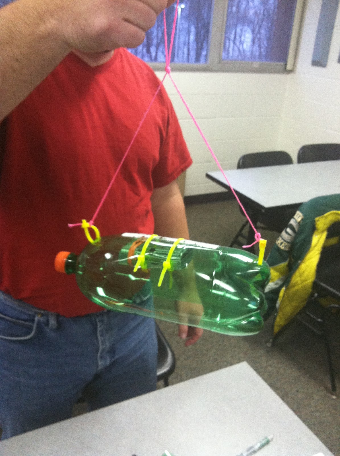 |
| Figure 3: 2 liter design. Camera is fastened with zip ties. A lense window is cut out of the bottom of the bottle. |
 |
| Figure 4: For the multi-shot function to work the shutter button must remain depressed. |
The second low altitude balloon uses a free floating camera
design housed in the top half of a vinegar jug (Figure 5). The advantage of this design is it lets the
camera behave independently of the balloon.
Ideally the images will be taken as near to vertical as possible to
allow for better image interpretation.
However, wind gusts may cause the camera to begin to swing creating
varying oblique’s making the process of mosaicking difficult.
 |
| Figure 5: Free floating camera design. |
High Altitude Balloon:
For this project the HABL design was primarily where I focused
my work. Similar to the low altitude
balloon, all resources used in its construction needed to be recorded and
weighed. However, with the HABL the
return trip also has to be accounted for.
A five foot parachute is being used to safely transport our payload box
back to the earth’s surface (figure 6). Knowing the
size of this parachute places certain limitations to the payload that can
added. If the box contains too much
material we run the risk of having a dangerous descent speed. We began testing our parachute with various
weights to record descent speed (figure 7).
 |
| Figure 6: A 5 foot parachute will be used to safely return our payload box. |
For retrieving the balloon a GPS tracker must also be included. With roughly estimate the balloon to travel up to 80 miles away from the launch site.
Deciding upon the
total weight of our payload was quite difficult. Every piece of string, rubber band, and
insulation had to be recorded to ensure an accurate total. It didn’t take long to have over two pounds
of material including the camera, heating packs, rope, and the GPS. Using this estimate, it was decided that our
balloon must be able to handle 2-4lbs.
While constructing the rig, the temperatures of our electronics
must also be controlled. If the
temperatures fall too low within our payload box we run the risk of losing battery
power to our equipment. To keep things
warm at 95,000 feet our payload box needs to be sealed, insulated, and supplied
with heating packs. However, this adds
another complexity to our project. The
lack of oxygen in that high of an altitude may have a negative effect on our
heat pack’s required chemical reaction. Our
current design uses a minnow bucket payload box with additional
insulation (figure 8). This first design is going to
begin certain stress testing shortly and will be modified accordingly.
Discussion:
As you can see above, this project is only in its preliminary stages. Our various designs have yet to be tested and modified. For the HABL construction I have a number of ideas to minimize weight. One of them being the use of a piece of heat blanket to substitute additional insulation. This could possibly keep the weight down as well as provide further reflectance of heat waves. Another idea I have for future development is using spray insulations. The benefit of this is all of the components would not require further securing in place. Additional holes could be cut into the styrofoam so that power buttons may be depressed. Further testing on spary insulation will be done to determine how much added weight it may cause.
Conclusion:
Now that we have a general idea of our balloon designs we can continue our preparation paying more attention to the details. Certain factors that may seem small are often what cause the most problems in the field. Things such as which knots to use and the best techniques for fastening our components together need more consideration. Pending test results we will continue improving on or possibly redesigning our constructions.
 |
| Figure 8: Cutting additional insulation to keep the equipment warm and working. |
Discussion:
As you can see above, this project is only in its preliminary stages. Our various designs have yet to be tested and modified. For the HABL construction I have a number of ideas to minimize weight. One of them being the use of a piece of heat blanket to substitute additional insulation. This could possibly keep the weight down as well as provide further reflectance of heat waves. Another idea I have for future development is using spray insulations. The benefit of this is all of the components would not require further securing in place. Additional holes could be cut into the styrofoam so that power buttons may be depressed. Further testing on spary insulation will be done to determine how much added weight it may cause.
Conclusion:
Now that we have a general idea of our balloon designs we can continue our preparation paying more attention to the details. Certain factors that may seem small are often what cause the most problems in the field. Things such as which knots to use and the best techniques for fastening our components together need more consideration. Pending test results we will continue improving on or possibly redesigning our constructions.
No comments:
Post a Comment